Software Development Kit V2 (SDK)
Introduction
Continuing in the success of the Touch Encoder Product Line, Grayhill is thrilled to announce the launch of its latest Touch Encoder Software Development Kit (SDK). With the Touch Encoder’s unique display, touchscreen, and rotary knob design, this multifunctional control is both sleek and rugged and fast becoming the user-interface choice for many industries such as Avionics, Marine, Ag/Con, Recreational Vehicles, Industrial and Luxury Automotive. Our new SDK, designed to work seamlessly with the graphics creation tool GUIDE, represents a significant leap forward, offering a more plug-and-play experience that simplifies your development process.
Features
Plug and Play Simplicity: Our SDK is engineered for effortless integration, requiring only power and USB-C cables to kickstart your development journey. Experience a smooth and hassle-free setup that streamlines your entire process.
Streamlined Communication for CAN J1939 customers: Say goodbye to third-party hardware dependencies when it comes to CAN J1939 communication. Our SDK eliminates the need for a separate piece of hardware, offering a unified solution that enhances both efficiency and cost-effectiveness.
Enhanced Development Speed: Accelerate your development timeline with our user-friendly SDK. Minimize setup complexities, allowing you to focus more on refining your application and bringing your ideas to market faster.
Package Contents
SDK
Power Cable (Grayhill PN: T11927)
USB A Male to Power Barrel (Type M), 2 meters long, 24 AWG
Power Adapter (Grayhill PN: T11928)
Power Adaptor Kit Wall to USB A Female
North America, Europe, United Kingdom, Australia, and China blade included
90 - 264 Vac
Part Numbers
SDKs are available with or without the Touch Encoder device itself. SDKs without the Touch Encoder can be useful for those who already have a Touch Encoder but would like the added functionality of the SDK, especially for CAN J1939 communication because it has an on-board CAN/USB adaptor, or for use as an update station for low volume production.


Under the Hood
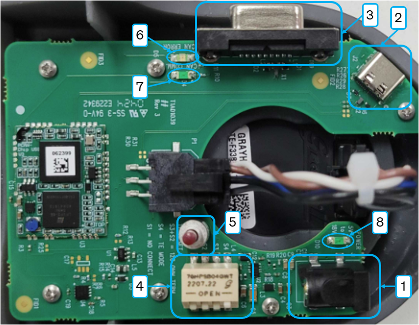
CAN J1939
Position # | Description | Function |
|---|---|---|
1 | Power Barrel (Type M) | Supplies Power to the SDK (5v-18v) |
2 | USB-C Female | On-board CAN J1939 Communication |
3 | DB9 Female | Bring your own CAN device |
4 | Mode Selection (Utility App vs. Run Mode) and Terminating Resistor | |
5 | Momentary Switch | Resets Device Power |
6 | CAN Error LED | Illuminates when a CAN bus error is detected |
7 | CANbus Status LED | Illuminates when data is being transmitted on the CANbus |
8 | Power Status LED | Illuminates when power is supplied to the SDK |

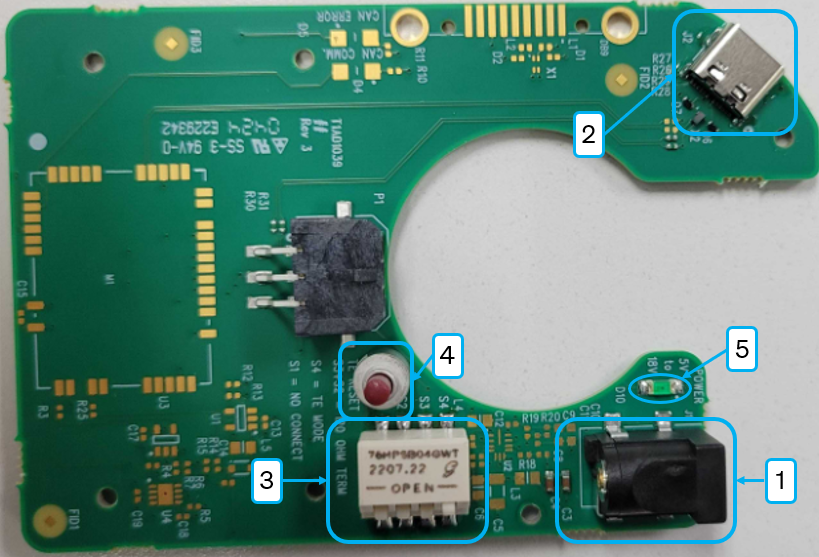
USB
Position # | Description | Function |
|---|---|---|
1 | Power Barrel (Type M) | Supplies Power to the SDK (5v-18v) |
2 | USB-C Female | USB Communication |
3 | Mode Selection (Utility App vs. Run Mode) | |
4 | Momentary Switch | Resets Device Power |
5 | Power Status LED | Illuminates when power is supplied to the SDK |

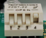
Dip Switch
Position # | Closed | Open | Description |
|---|---|---|---|
1 | No Function | No Function | No Function |
2 | Active | Inactive | 120 Ohm Terminating Resistor |
3 | Active | Inactive | 120 Ohm Terminating Resistor |
4 | Run Mode | Mode on next re-boot |
Pins 2 and 3 have No Function on the USB versions of the SDKs. On the CAN J1939 version, both pin2 and pin 3 must be in the Closed/Active position to ensure the correct terminating resistor value per the CAN J1939 specification.
